WEDNESDAY 30 OCTOBER 2019
Projected Capacitive Touch Sensor
Touchscreen technology is everywhere and already plays a major part in our everyday lives. From its dominance in consumer electronics, such as smartphones, tablets and mobile devices, to ATM machines, point-of-sale terminals and games consoles, touchscreen technology now has a significant impact on enhancing the Human Machine Interface (HMI) in more industrial and B2B applications. By no means a new invention - the first touchscreen was conceived in the 1960s – this technology has undergone considerable change since then. From the early iterations of resistive touchscreens relying on resistance and pressure to the introduction of surface capacitive technology and beyond to Projected Capacitive Touch (PCT) sensing for a more responsive experience, touchscreen technology has moved on significantly in recent years.
This White Paper focuses on the benefits of PCT sensing technology and provides a comprehensive overview of the latest tried and tested PCT solutions, outlines their benefits, offers guidance on selection, installation, and integration, and includes appendices with more detailed information, test analysis, and reference material.
Why projected capacitive touch sensing technology?
In simple general terms, a capacitive touchscreen panel consists of an insulator coated with a transparent conductor.
Since the human body acts as an electrical conductor, touching the surface of the screen results in a distortion of the screen’s electrostatic field, which is measurable as a change in capacitance.
Projected Capacitive Touch (PCT) is a variant of capacitive touch technology, comprising a matrix of rows and columns of conductive material layered on sheets of glass, allowing for a more accurate and flexible operation. This is achieved by creating a conductive layer in the form of an X-Y grid by either etching one layer to form a grid pattern of electrodes or by etching two separate parallel layers of conductive material with perpendicular lines or tracks to form the grid. This configuration is comparable to the pixel grid found in many liquid crystal displays (LCD).
With a configurable activation force, PCT sensors can accommodate cover lens designs. Because of this top layer of PCT cover glass, it delivers a more robust solution versus resistive touch technology. This offers greater protection against harsh operational environments, including the presence of surface contaminants.
Depending on implementation requirements, an active or passive stylus can be used instead of, or in addition to, a finger. Furthermore, it is capable of responding to thick-gloved touch in applications where users need greater personal protection.
As legacy resistive touch technology is phased out, PCT is being increasingly adopted for industrial display uses.
Mutual capacitance PCT versus self-capacitance PCT
There are two types of PCT solutions: Mutual Capacitance and Self Capacitance.
In mutual capacitive sensors, a capacitor is inherently formed at the intersection of each row and column. For example, a 12-by-16 array would have 192 independent capacitors. A voltage is applied to the rows or columns. Bringing a finger or conductive stylus near the surface of the sensor changes the local electrical field, reducing the mutual capacitance. The capacitance change at every individual point on the grid is then measured, and the voltage in the other axis is monitored to pinpoint the touch location. This allows for multi-touch operation where multiple fingers, palms, or styli can be accurately and simultaneously tracked.
Self-capacitance sensors can have the same X-Y grid as mutual capacitance sensors, but the columns and rows operate independently. With self-capacitance, the capacitive load of a finger on each column or row is sensed by measuring changes in the current. While this produces a stronger signal than mutual capacitance sensing, it is unable to accurately resolve more than one touch, resulting in “ghosting” or misplaced location sensing.
Since the human body acts as an electrical conductor, touching the surface of the screen results in a distortion of the screen’s electrostatic field, which is measurable as a change in capacitance.
PCT Sensor Technologies
PCT sensor technology can be constructed in several ways. Emerging trends and technologies, however, have seen cutting-edge design using On-Cell Touch and In-Cell Touch, where the integrated structure and touch functionality are embedded in the display itself rather than on a separate touch screen component mounted above it.
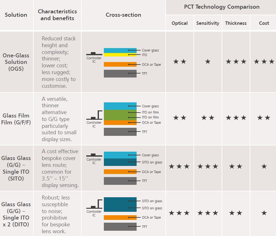
Four most common and proven sensing technologies
The Benefits of PCT
- Multi-touch capability
- Low activation force
- Sensing through cover window materials of varying thickness
- Enhancing the HMI to create a more consumer-based look and feel
- Integration of complex artwork printing and lens design features
- Maximum optical clarity, no shape loss or deformation over time
- Chemical and scratch resistant
- No drift over time, eliminating the need to re-calibrate
- Extending the lifetime of a product through increased durability
- Availability in a variety of glass structures, from GG (Glass/Glass) to OGS (One-Glass Solution) and GFF (Glass/Film/Film).
A Total Solution Approach
Key Considerations
When integrating PCT sensor technology and display modules into a system, it is essential to treat the process as a final product development design and consider the various constituent sub-systems. It is simply not a case of adding the PCT layer and expecting a straightforward, hassle-free operation. Every alternative combination of display, mechanics, sensor, and the internal PCB, will result in a fundamentally different operation of the same sensor.
Consideration should therefore be given to all aspects that constitute the overall product development design.
These include:
- PCT sensor
- Outer cover window/lens surface
- Display
- Mechanical housing
- Touch Controller Chip or Controller Board (either integrated with the sensor – COG/COF or an external PCB)
- Firmware - the control software embedded within the touch controller
- Driver – the software used to interface with the firmware and give the necessary touch information
- Placement within the system to minimise electrical and noise interference
Selecting the right Cover Lens material
Selecting the right material for your cover lens is essential to achieve optimum results, and there is a wide range of materials to choose from. The final choice will very much depend on its end use, its intended application, and its operational environment with options to solve a range of client challenges, such as anti-vandalism, wide temperature operation, sunlight readability or the need for unique shapes and bespoke designs.
The two most common material categories are glass and plastic.
Glass
- Basic Soda Lime Glass
- Chemically strengthened.
- Heat-strengthened
- Toughened (also known as Tempered glass).
- Gorilla Glass, Dragon Tail, NSG
Plastic
- Acrylic (PMMA)
- Polycarbonate (PC)
- Optolite™ HSR (High Scratch Resistant
The Dielectric Constant
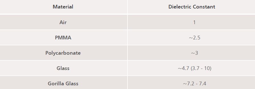
As part of the total solutions, or end product development approach, consideration needs to be given to the dielectric constant of the cover lens material selected. The cover lens is the main item of the capacitor dielectric between the finger and the electrode. Thus it is important to take into account this dielectric constant when making touch designs, as each different material typically alters the touch sensitivity.
The higher the dielectric, the better the propagation. Therefore, a 5mm cover lens with an εr of 8 will perform similarly in sensitivity to a 2.5mm lens cover with a value of 4 if all other environmental factors are constant.
Points to remember:
- Select a cover lens material with a high dielectric constant – glass is a good example.
- Avoid air gaps between the sensor and cover lens by reducing the clearance between the two components or using an Optical Bonding layer.
- Use the thinnest cover lens viable for the application.
- Ensure the Touch Controller is calibrated for full thickness, including the cover lens.
Important industry standards
Careful consideration must be given to the outer surface of the finished product, whether comprising the external PCT cover lens or an additional overlaid window material. The following outlines a number of important industry standards relating to surface hardness, moisture ingress, drop testing and sealing.
- Mohs Hardness Scale
- IP rating system
- NEMA rating
Mohs Hardness Scale
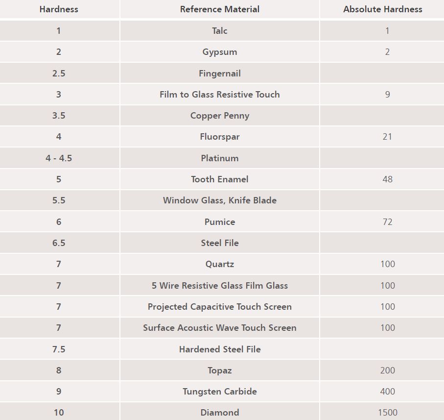
The Mohs scale is used to measure the relative hardness of a mineral by its resistance to scratching. Mohs hardness is measured on a scale from 1 to 10, with softer minerals having low numbers and harder minerals having higher numbers.
The Mohs Hardness table below shows a comparison; with the absolute hardness measured by a sclerometer of common materials. Further information on the Mohs Hardness Scale is available in the appendices at the end of this document.
Mohs Hardness Scale
IP Rating System
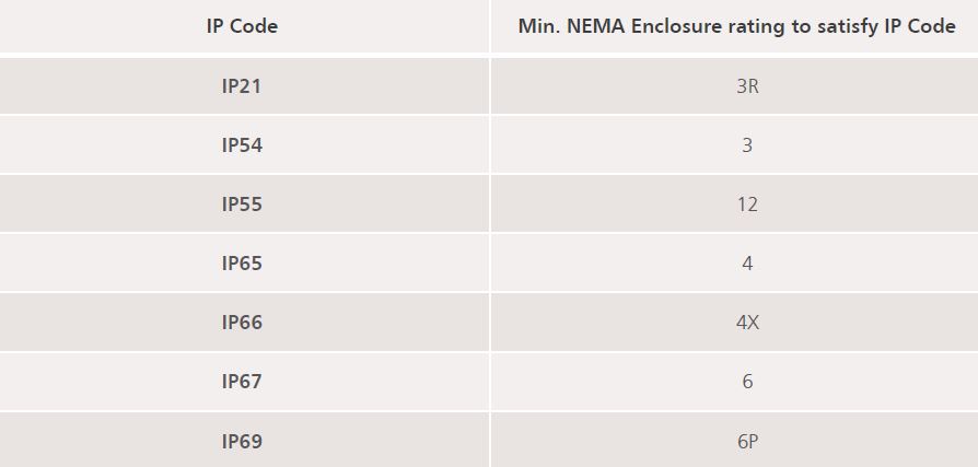
The IP (Ingress Protection) rating (IEC standard 60529) is international protection marking used to classify and define levels of sealing effectiveness and the degree of protection of electrical enclosures against intrusion from foreign bodies (tools, dirt etc.) and moisture. The IP Rating system is published by the International Electrotechnical Commission (IEC), and the equivalent British standard is known as EN 60529.
Further information on the IP rating system, including additional tables on liquid ingress, mechanical impact resistance and solid particle protection, is available in the appendices at the end of this document.
NEMA Rating
The National Electrical Manufacturers Association defines NEMA enclosure types in NEMA standard number 250. Ratings are not directly equivalent between the two standards, but the following table outlines the NEMA ratings that would correspond to the performance required by an IP code.
NEMA ratings also require additional product features and tests (such as functionality under icing conditions, enclosures for hazardous areas, knock-outs for cable connections and others) not addressed by IP ratings.
IP Code
Installation & Integration Advice
- Always use the best quality power supplies. The voltage regulator must provide a stable voltage without any ripple. The actual precision of the voltage is not important, but the noise rejection feature is critical.
- The voltage regulator, which also acts as a filter against noise from the power supply, should be positioned as far as possible from the sensors and their tracks. It is also recommended to power any switching components, such as LEDs, directly from the VDD supply and NOT from the regulated voltage.
- Avoid common-mode voltages
- Always implement grounding to Earth: A metal chassis behind a touch sensor is a good path to the ground and tends to reduce the sensitivity of the touch response in case there is a significant area of overlap. Such a metallic surface must never be electrically floating as it makes the whole product unstable in terms of touch detection. This is also applicable to any conductive decorative feature close to the sensor.
- Be cautious using metallic paints: Metallic paints can be an issue if they contain
- conductive particles. Low particle density
- paint is therefore recommended.
- Select a display with low noise characteristics: focus on smart backlight designs with consideration to the number of LED nodes. Avoid CFL tubes or EL backlight sources and/or high-voltage inverters.
- Touch controller selection: A high-SNR signal-to-noise ratio touch controller increases touch accuracy because it enables stronger signal readings from touch and collects sample data from a larger surrounding area.
- Be aware of hardware noise sources: These can include LCD displays, any WiFi antennas, GPS antennas, and AC adapters or AC components and circuits.
The Reflection Dilemma
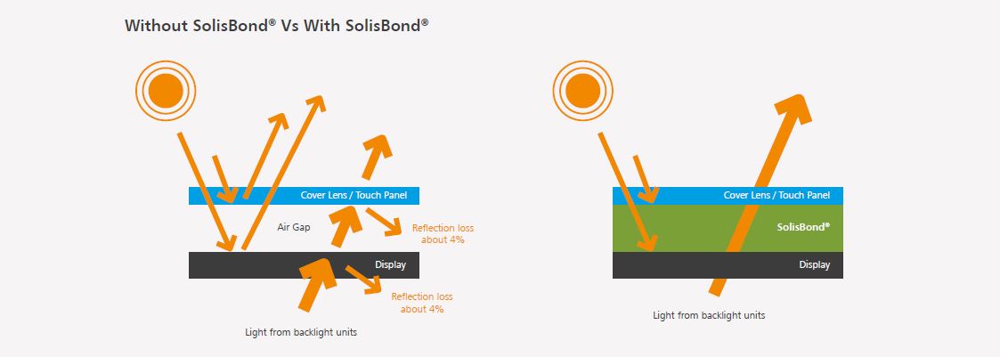
Adding additional substrate layers to a display imparts additional internal light refraction and external reflection. This results in a loss of ambient incident light, leaving the solution looking grey and lacking contrast, especially when operating in an outdoor environment or under bright lighting conditions.
The industry-standard method for bonding a touch or glass substrate to a display uses tape gasket bonding. However, this will result in one or two air gaps between the touch sensor and the display. In indoor environments or in low light conditions, the impact of these air gaps may not be so apparent, but this becomes very evident when ambient light levels are increased.
The benefits of Optical Bonding:
- Improved sunlight readability
- Shock-resistant
- Enhanced contrast and colour saturation
- Re-workable
- Ease of application/process cost-effective
- Flexible solutions - Bond Glass, Polycarbonate and Acrylic
- - All types of displays, touch panels and cover plates
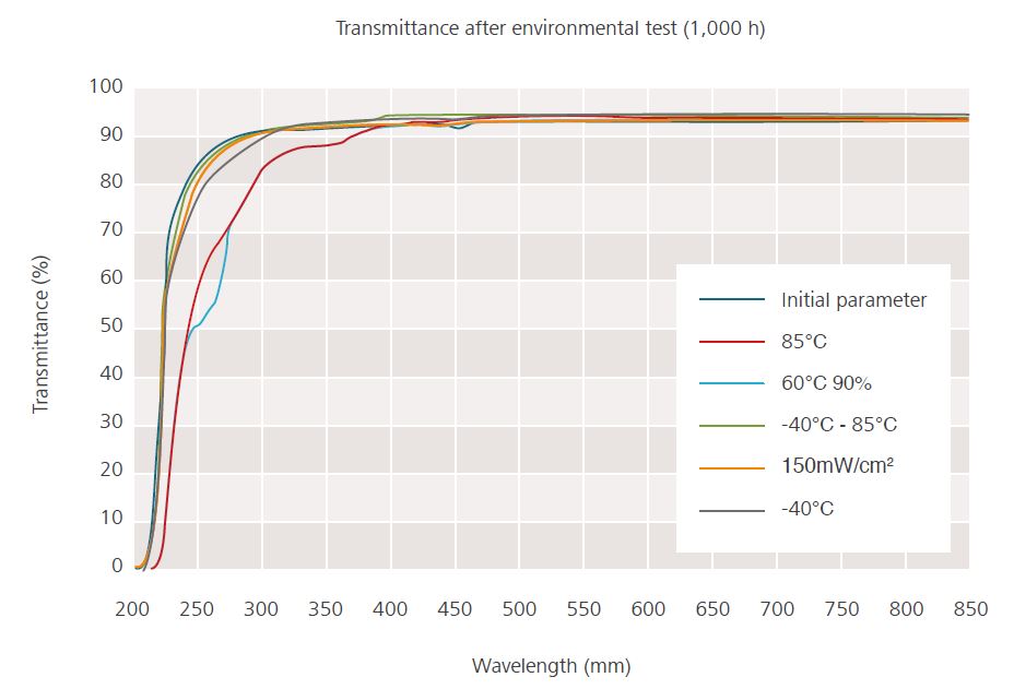
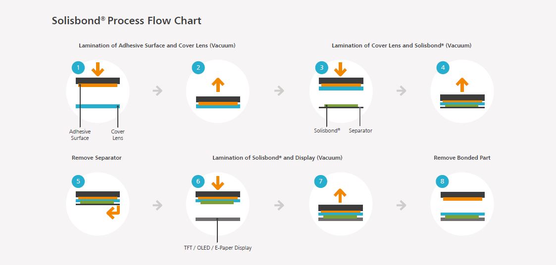
Optical Bonding: Further information and test analysis results on Optical Bonding and SolisBond® Technology is available in the appendices at the end of this document.
Gasket and Mounting - Integration Design Guidance
A Rear Mount Design
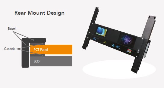
A rear-mounted design covers scenarios where the PCT and display module are mounted behind a front Bezel using a Gasket. In this situation, it is recommended to use a non-conductive adhesive for the Gasket. Gaskets can be applied in a continuous or strip format.
Continuous gaskets between the top of the touch screen and the bezel are recommended to avoid the ingress of water and debris.
The bezel and enclosure can also be designed to prevent water from pooling along the edges.
The minimum distance between the touch screen and LCD is generally 0.25-28 mm, but LCD noise interference could increase this distance requirement. In addition, experimenting with clearance between the PCT and display, using varying Gasket thickness, will help to reduce noise further.
A Front Mount Design
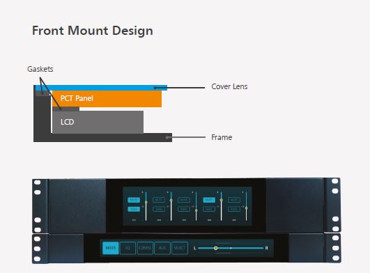
Bezel-less integration is similar to how many smartphones are designed and is now a popular methodology for industrial design.
A lens made of glass is bonded to the front surface of the touchscreen for extra durability and aesthetics. A frame around the edge of the lens is required for mechanical support. The frame can be made of plastic or metal, but the same guidelines as the rear mount design exist.
The Densitron PCT Total Service Solution
DensiTouch™
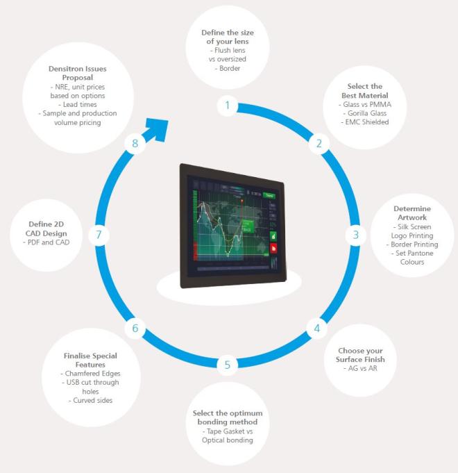
Densitron handles all of its PCT designs as individual projects and brings extensive knowledge, expertise and technical support to ensure its technologies deliver maximum functionality, optical clarity, durability and longevity. Its years of product knowledge, expertise in design and engineering and ongoing commitment to research and development ensures Densitron continues to push the boundaries to deliver state-of-the-art solutions that meet existing needs and anticipate future demands.
Our full-service total solutions offering comprises:
- The latest multi-touch PCT panel technology – including thick-gloved activation for harsh industrial environments
- Cover Lens manufacture, customisation and light reflection solutions
- Fully integrated PCT TFT display units using state-of-the-art technologies
- Customisation for bespoke PCT Sensors
- Calibration optimisation services
- Extensive research, development and testing facilities, including expert engineering for the manufacture of hard tooled stencils and bespoke testing jigs
Appendices
Appendix 1:
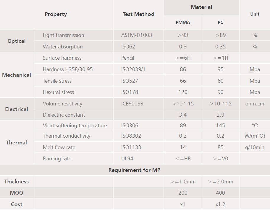
Analysis of plastic lens material – PMMA (Acrylic) v PC (Polycarbonate)
Guidance notes for design engineers attempting to select between PMMA and PC.
1. PMMA has 17 times the impact resistance of glass compared to PC which is 250 times more impact resistant
2. PMMA is extremely rigid whereas PC is available in flexible grades
3. PPMA cracks more easily than PC under
stress conditions
4. Compared to glass, the light transmittance of PMMA is 92% compared to 88% for PC
5. PMMA can be polished to restore clarity and its edges polished smooth if required. This is not possible with PC.
6. PMMA can handle temperatures up to 88°C.
PC can handle temperatures up to 115°C
7. PMMA will crack if drilled near an edge or without a specifically designed drill bit. PC typically does not crack when drilled, even if close to the edge and using a standard drill bit.
8. PC has a higher chemical resistance than PMMA
9. PMMA is more likely to chip than PC because it is less impact-resistant. It does not scratch easily, however, and will not yellow over time.
10. PC has low flammability. PMMA however will burn slowly and is therefore not recommended for use where flames may be present
11. PC is more expensive, on average costing approximately 35% more than PMMA.
12. Due to the expansion coefficient of PC, it does not lend itself well to Optical Bonding processes. Temperature cycling usually leads to bubbles
and other spurious unwanted phenomena in
the final product.
Control Systems
Appendix 2: The Mohs Scale
The Mohs scale of mineral hardness characterises the scratch resistance of various minerals through the ability of a harder material to scratch a softer material.
It was created in 1812 by the German mineralogist Friedrich Mohs and is one of several definitions of hardness in materials science.
The scale is based on ten minerals. Diamond, the hardest known naturally occurring substance, is at the top of the scale with a Mohs score of 10. At the other end of the scale, Talc has a Mohs rating of just 1.
The hardness of a material is measured against the scale by finding the hardest material that the given material can scratch, and/or the softest material that can scratch the given material. If for example some material is scratched by a fingernail but not by penny, its hardness on the Mohs scale would fall between the two.
Appendix 3: The IP Rating System
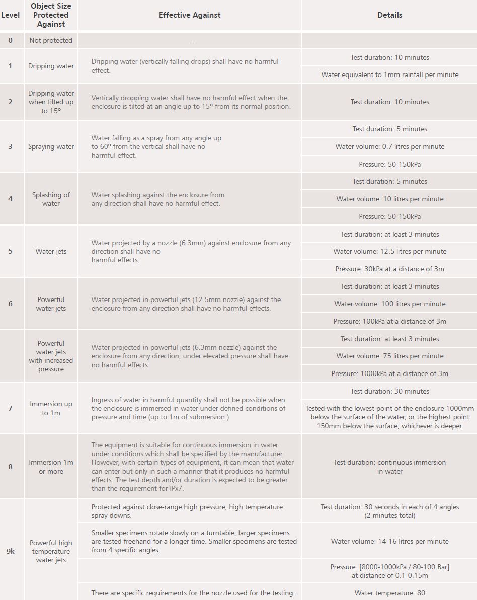
The standard aims to provide more detailed and accurate information than vague marketing terms such as waterproof. The digits (characteristic numerals) indicate conformity with the conditions summarised in the tables below. Where there is no data available to specify a protection rating with regard to one of the criteria, the digit is replaced with the letter X. The digit 0 is used where no protection is provided.
A rating of X for one or more of the protection criteria can be erroneously misinterpreted as “no protection”. To illustrate, a piece of electronic equipment rated IPX7 will almost certainly demonstrate a robust resistance to the ingress of particles, even though a rating
for ingress of solids hasn’t been formally assigned. Hence, an X designation shouldn’t be automatically misconstrued as a lack of protection.
For example, an electrical socket rated IP22 is protected against insertion of fingers and will not be damaged or become unsafe during a specified test in which it is exposed to vertically or nearly vertically dripping water. For example, a particular cellular phone rated at IP58 is “dust resistant” and can be “immersed in 1.5 metres of freshwater for up to 30 minutes”. IP22 or 2X are typical minimum requirements for the design of electrical accessories for indoor use.
The ratings for water ingress are not cumulative beyond IPX6. A device which is compliant with IPX7, covering immersion in water, need not be compliant with IPX5 or IPX6, covering exposure to water jets. A device which meets both tests is indicated by listing both tests separated by a slash, e.g. IPX5/IPX7.
There are no hyphens in a genuine IP code. IPX-8 (for example) is thus a false IP code.

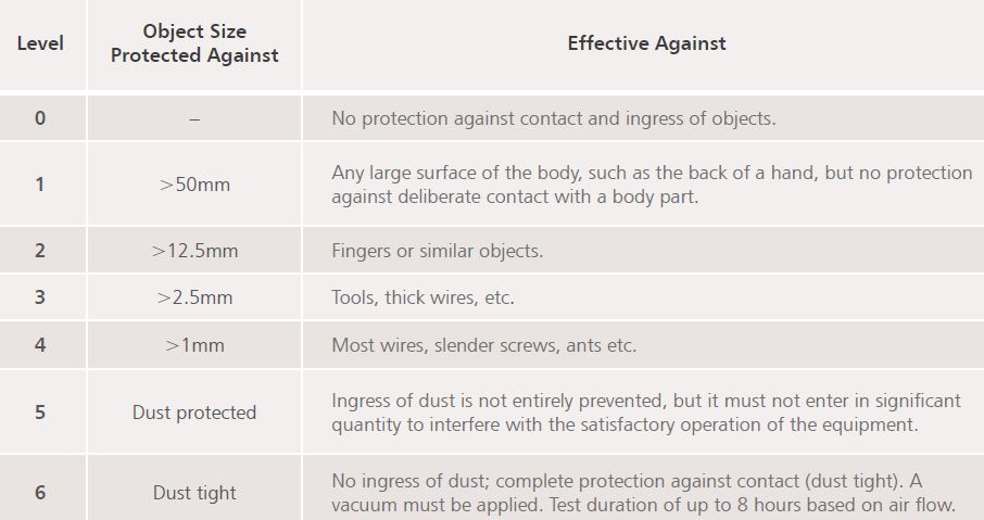
Solid Particle Protection
The first digit indicates the level of protection that the enclosure provides against access to hazardous parts (e.g., electrical conductors, moving parts) and the ingress of solid foreign objects.
Liquid ingress protection
The second digit indicates the level of protection that the enclosure provides against harmful ingress of water. For the rating system please see table below.
Resistance to Mechanical Impact
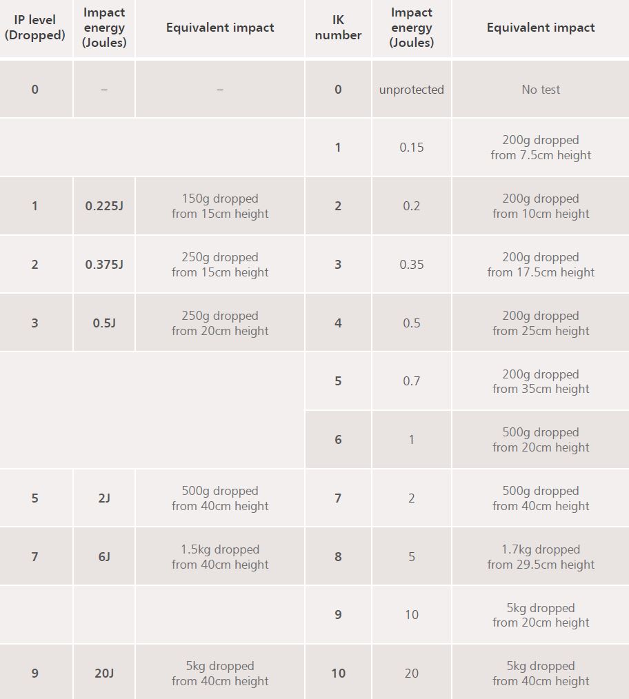
An additional number has sometimes been used to specify the resistance of equipment to mechanical impact. This mechanical impact is identified by the energy needed to qualify a specified resistance level, which is measured in joules (J). This has now been superseded by the separate ‘IK code’ specified in EN 62262.
Although dropped from the 3rd edition of IEC 60529 onwards, and not present in the EN version, older enclosure specifications will sometimes be seen with an optional third IP digit denoting impact resistance. Newer products are likely to be given an IK rating instead. However, there is not an exact correspondence of values between the old and new standards.
Contact us
For more information about Densitron or any of our products and services please contact one of our regional offices or contact@densitron.com

.jpeg)


